Hello,
this is my teardown of the WT1 2 channel CCT LED controller. This is a device intended to dim WW/CW strips (CCT mode) but it can be also used as a 1 channel dimmer (DIM mode). One can control it using the Tuya app, dedicated remote control, or a physical push button. The protocol used for remote control is WiFi.
The device is similar to the WT5 Multi-Channel LED controller described in a different Elektroda forum thread. But the whole OpenBeken installation process was not described step-by-step there so I thought I would cover that in this post.
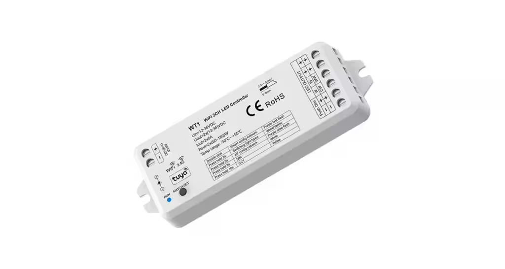
The WT1 controller contains the WB3S chip which connects to WiFi. Additionally, there is also a chip labeled sc95f8615p. It is connected to WB3S via the TXD1 and RXD1 pins and communicates with it using the TuyaMCU protocol.
This latter Tuya MCU chip then controls:
- the PWM output for the LED strips,
- RF communication with the dedicated remote controllers,
- the physical button controls,
- and even switching between the CCT and DIM modes.
So by flashing the WB3S, we do not lose any of these capabilities and only get rid of the dependency on Tuya cloud.
My approach was to:
- Disassemble the device, solder pins for flashing.
- Flash OpenBeken firmware using a USB-TTL converter and the BK7231 GUI Flash Tool.
- Configure the device using the web interface.
Disassembly
The disassembly is simple. The white case contains no screws and is held together by clips. Simply pry open the bottom part of the case and you can access the insides.
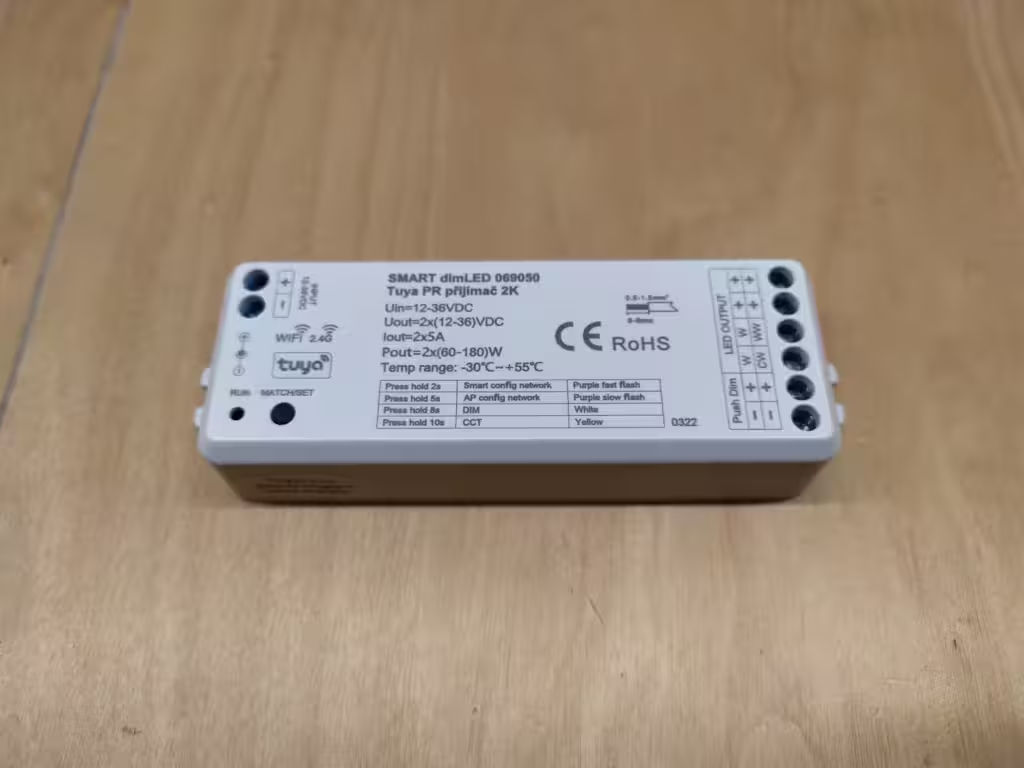
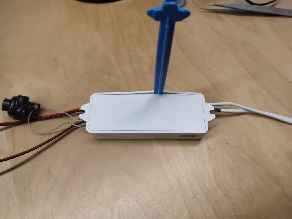
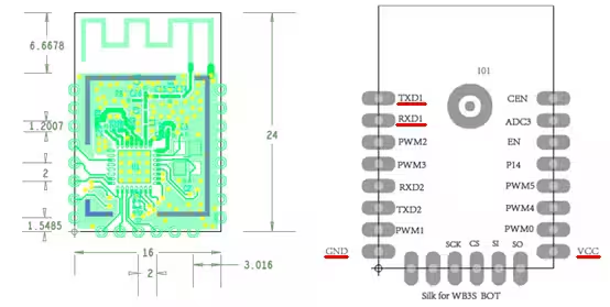
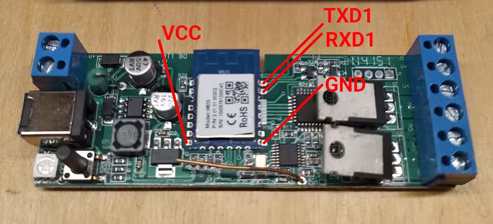
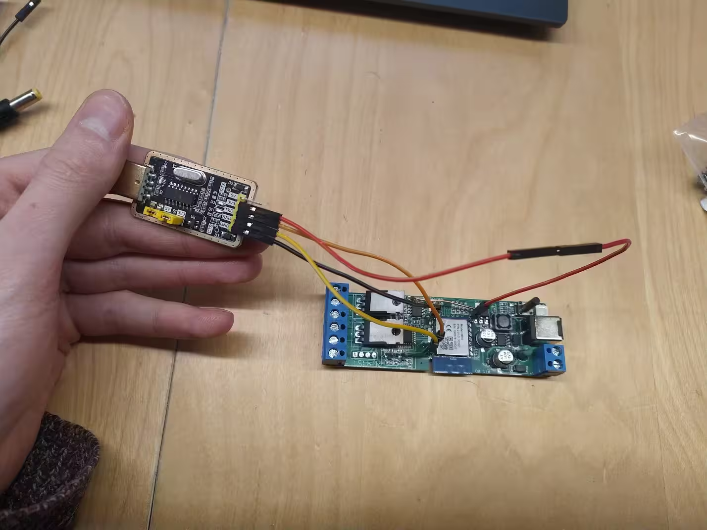
As mentioned, inside we find the WB3S chip along with a second chip that controls the PWM. We need to solder 4 pins as shown in the third image. For this I used DUPONT pins and soldered them directly to the WB3S chip pads.
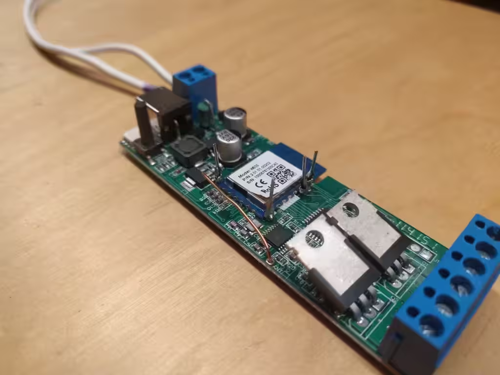
Then I was able to connect the USB to TTL converter. I used a CH340 based module from Aliexpress that has a 3.3V mode. Using a jumper, I set the 3.3V output on the converter and connected the pins to the WB3S chip:
- VCC <-> 3.3V
- TXD1 <-> RXD
- RXD1 <-> TXD
- GND <-> GND
For the VCC connection, I used two wires, so that disconnecting and reconnecting the power would be easy. This comes useful later in the flashing part.
For flashing, I wanted to use the nice and beginner friendly BK7231 GUI Flash Tool. I downloaded the last version from Releases in Github.
Because I run Linux, I needed to run the application in a local virtual machine with Windows 11. This part is therefore a bit specific to my setup and most people running Windows natively may skip the VirtualBox setup (skip the next paragraph).
I connected the CH340 to my laptop and checked that the Serial port appeared as /dev/ttyUSB0. In VirtualBox, I enabled the serial port through Machine Settings->Serial Ports->Port 1. There I set the following:
- Port Number: COM1
- Port Mode: Host Device
- Path/Address: /dev/ttyUSB0
(Note: I also tried to expose directly the USB device to the guest system but didn’t have success flashing the image that way)
(Second note: maybe one could run the flashing tool using Wine but I didn’t attempt that)
I started the flash tool and the serial (UART) port was detected automatically as COM1. I also set the chip type to BK7231T (=WB3S) and set the Baud Rate to 115200 (the default value was crashing). Finally, I selected the “Do backup and flash new” option and everything went smoothly. During the flashing, the device needed to be rebooted two times. I did this by replugging the VCC cable.
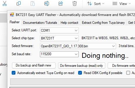
For a more detailed flashing guide, I refer you to the Flash tool README.
After flashing the device, the OpenBK-... access point showed up on my WiFi scan. I connected to the network and accessed http://192.168.4.1 in my browser.
There I went to Launch Web Application -> Filesystem.
I prepared a file called autoexec.bat with the following contents:
startDriver TuyaMCU
tuyaMcu_setBaudRate 115200
tuyaMcu_defWiFiState 4
tuyaMcu_setupLED 24 0
And Iuploaded the file to the device by drag-and-drop to the Web UI and rebooted the controller.
Now on http://192.168.4.1/ I see LED controls and they work!
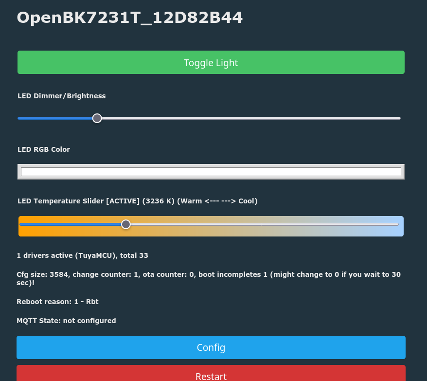
Note that this setup assumes that you switch to the CCT mode by holding the mode switch button for 10 seconds.
Finally, I also edited the Wifi settings through Config -> Configure Wifi so that the dimmer connects to my home wifi. The next step is to configure MQTT and integrate the device with your home automation system.

Leave a Reply