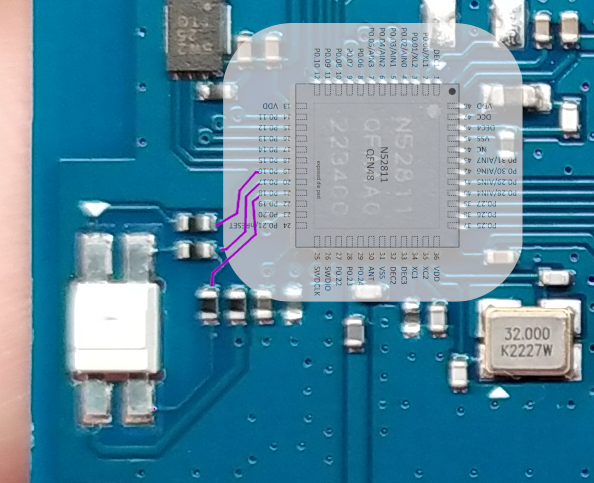
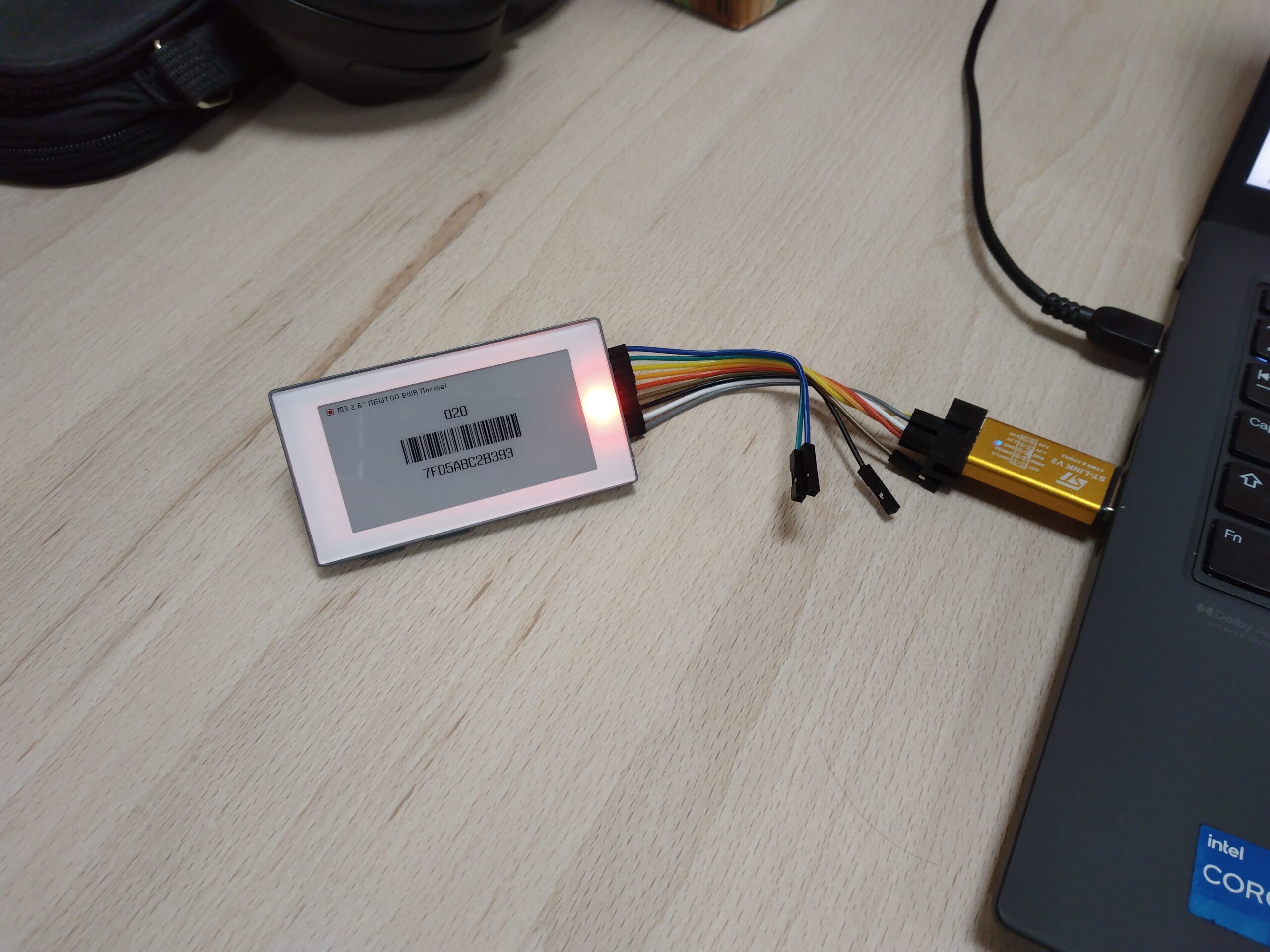
In this post, I describe how to set up a development environment to write a custom firmware for the Solum Newton M3 e-ink label. The device is based on the nRF52811 SoC and we will use the official nRF Connect framework.
In the first part of this series, I described the internals of the Solum electronic label and how to dump the original firmware. Today, we will:
- Install the nRF Connect framework project
- Create and configure an example project
- Flash the firmware using the ST-Link debugger
Related work
OpenEPaperLink is an alternative firmware for e-paper shelf labels. Firmware for nRF52811-based tags is available and supports the Newton M3 label.
In this post, I want to provide pointers for developing a simpler, custom firmware, possibly utilizing the additional features of Newton labels such as buttons and RGB LED.
Installing nRF Connect
I basically followed the official tutorial video series on installing nRF Connect for VS Code. I created a separate profile in VS Code to separate this project from my other work.
During installation, I encountered a problem with libunistring.so.2: cannot open shared object file. I found a forum thread mentioning this problem and created the following symlink to fix it:
ln -s /usr/lib/libunistring.so.5 /usr/lib/libunistring.so.2It is not the cleanest solution but it works.
Creating the first project

After installing nRF Connect, I created a new application from the Blinky Sample example project (nRF Connect -> Welcome -> Create a new application -> Copy a sample). Then I added a build configuration with the Board target Nordic nRF52840 DK NRF52811.
Then, I made three changes to make the example project run:
- I created a device tree source overlay to define the LED pins on the Solum board.
- I modified
main.cto use these pins. - I set the clock source to RC oscillator instead of crystal.
The dts overlay can be created in nRF Connect -> Build -> Config files -> Devicetree -> Create overlay file. This creates a new file called nrf52840dk_nrf52811.overlay in the project root folder. There I added the following definitions:
/ {
    leds {
        compatible = "gpio-leds";
        led_r: led_r {
            gpios = <&gpio0 16 GPIO_ACTIVE_LOW>;
            label = "Red LED";
        };

        led_g: led_g {
            gpios = <&gpio0 17 GPIO_ACTIVE_LOW>;
            label = "Green LED";
        };

        led_b: led_b {
            gpios = <&gpio0 18 GPIO_ACTIVE_LOW>;
            label = "Blue LED";
        };
    };
};
In main.c, I changed the LED0_NODE to:
#define LED0_NODE DT_NODELABEL(led_r)After these changes, the code was building without errors. But after flashing, the board was not blinking. By setting up breakpoints in GDB I found that the firmware does not reach the main() function and is stuck in an infinite loop waiting for clock inicialization:
$ arm-none-eabi-gdb
GNU gdb (GDB) 14.2
...
(gdb) file /home/jirka/ncs/projects/blinky_1/build/zephyr/zephyr.elf
Reading symbols from /home/jirka/ncs/projects/blinky_1/build/zephyr/zephyr.elf...
(gdb) target extended-remote :3333
Remote debugging using :3333
__set_BASEPRI (basePri=32) at /home/jirka/ncs/v2.7.0/modules/hal/cmsis/CMSIS/Core/Include/cmsis_gcc.h:1315
1315	  __ASM volatile ("MSR basepri, %0" : : "r" (basePri) : "memory");
(gdb) run
The program being debugged has been started already.
Start it from the beginning? (y or n) y
Starting program: /home/jirka/ncs/projects/blinky_1/build/zephyr/zephyr.elf

^C
Program received signal SIGINT, Interrupt.
arch_cpu_atomic_idle (key=key@entry=32) at /home/jirka/ncs/v2.7.0/zephyr/arch/arm/core/cortex_m/cpu_idle.c:133
133		arch_irq_unlock(key);
(gdb) n
135		__enable_irq();
(gdb)
lfclk_spinwait (mode=CLOCK_CONTROL_NRF_LF_START_STABLE)
    at /home/jirka/ncs/v2.7.0/zephyr/drivers/clock_control/clock_control_nrf.c:523
523			    && (nrf_clock_lf_src_get(NRF_CLOCK) == NRF_CLOCK_LFCLK_RC)
(gdb)
507		while (!(nrfx_clock_is_running(d, (void *)&type)
(gdb)
514				if (isr_mode || !IS_ENABLED(CONFIG_MULTITHREADING)) {
(gdb)
515					k_cpu_atomic_idle(key);
(gdb)
...
... infinite loop ...
...
I found that this might be related to clock settings. The problem can be mitigated by setting a different clock source instead of Crystal Oscillator. This can be done in VS Code: nRF Connect -> nRF Kconfig GUI -> Device Drivers -> Clock controller drivers -> NRF Clock controller support -> 32KHz clock source -> RC Oscillator, then click Save to File.
Alternatively, add the following setting to prj.conf:
CONFIG_CLOCK_CONTROL_NRF_K32SRC_RC=ySadly, I am not sure why we need to switch to RC Oscillator because it seems to me that there is an external crystal on the board connected to the XC1 and XC2 pins. If anyone knows why this setting does not work, please let me know!
Flashing nRF52811 using ST-Link v2
Nordic recommends and supports using the SEGGER J-Link debugger to program their SoCs. I only had ST-Link v2 around and so I tried to use it instead of the J-Link.
By using OpenOCD with the correct configuration files, flashing an image should work by running:
openocd -f interface/stlink-dap.cfg -f target/nrf52.cfg -c "program ncs/projects/blinky/build/zephyr/zephyr.elf verify reset; exit"If you want to debug the firmware, drop the exit at the end and connect to the GDB session using:
$ arm-none-eabi-gdb ncs/projects/blinky/build/zephyr/zephyr.elf
(gdb) target extended-remote :3333
Conclusion
And that is it! After following this guide, you should see your Solum electronic label blink. Next time we will look into how to interface with the e-ink screen.


Leave a Reply